 Click here for a simplified schematic diagram of the heater.
EBERSPACHER BN-4 GAS HEATER
by Jim Mais
©
1999
This model heater uses a glow plug and a spark plug to ignite the fuel. A single control relay (labeled CR) controls the fan motor and fuel pump. There are several safety circuits. Battery voltage (12V) is available at all times to the heater.
When heat is desired, the ON/OFF switch (or timer) is closed and relay CR operates. Assuming that the heater is in the cold state, the thermo-switch is closed to the NO (cold) terminal. The path thru CR (term M & J) and the thermo-switch energizes the glow plug. The fan motor also starts at this time. There are two fans. One pulls in combustion air and the other blows room air over the heat exchanger.
The spark coil is also energized . While the glow plug is heating, the
flame safety heater also is energized. If combustion does not take place
in a reasonable time
(2 to 3 minutes), the heater will be shut down (by de-energizing relay CR)
and no more fuel will flow. After waiting for the safety switch to cool down
(1 minute) the reset lever may be pressed to restart the heater.
While the glow plug is heating up, the fuel pump begins to deliver fuel. The fuel pump is a solenoid operated device. A set of points on the fan shaft open and close (thru a reduction gear) and trigger the fuel pump solenoid on and off. Each pulse of the solenoid delivers a tiny quantity of fuel to the heater. (Note that the solenoid is polarity sensitive; if the wires are reversed, it will not pump.)
Fuel quantity is adjustable by turning the threaded fitting on the pump discharge side. Screwing it in will decrease fuel quantity.
The fan shaft also has a set of points to operate the spark coil. Worm gearing from the shaft rotates the cam for the fuel pump trigger contacts. The fuel pump trigger occurs once for each 33 spark impulses. When the glow plug reaches operating temperature, the fuel should begin igniting. The thermo-switch senses the increased temperature in the heat exchanger and its contacts switch over. This opens the path to the glow plug and also to the flame safety heater. Combustion continues without the glow plug.
The spark coil continues to provide spark impulses as long as the heater
is running.
The heater will continue to operate until the operator switches off the power
or the Temp Regulating control (Temp Reg) opens the circuit. In either event,
CR will drop out, stopping fuel flow. The fan continues to run, however,
to purge the heat exchanger. The fan obtains power directly from the
thermo-switch.
When the heat exchanger cools down, the fan stops as the thermo-switch changes over to the Cold position. Now the heater is set to re-start if the ON/OFF switch is closed. The heater will cycle on and off automatically under the control of the Temp Reg control. Each time, the fan will continue to run until purge has been completed and then the glow plug will re-energize in preparation for another ignition cycle.
The safety fuse is built into the heater. In case of control failure and subsequent over heating, the Over-Heat thermal switch closes. This short circuits the Safety Fuse directly to ground. The fuse blows and the fuel pump can not receive power.
Click here for a simplified schematic diagram of the heater.
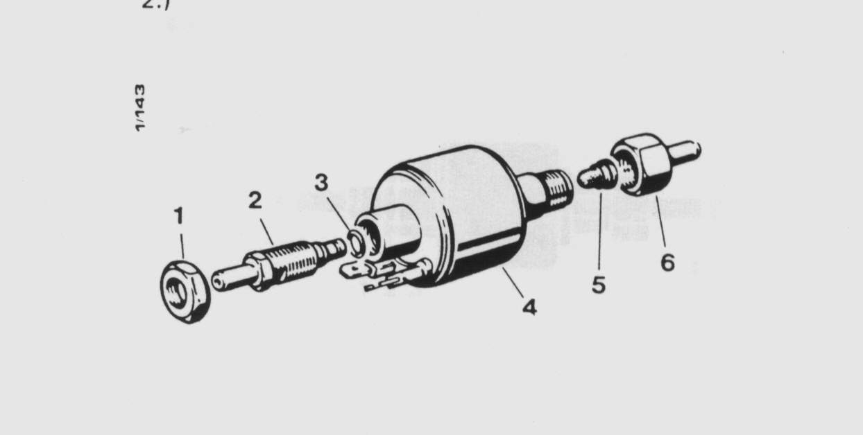 Picture of the impulse-style fuel pump.
![]()